
Introducting: AG3
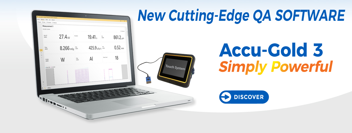
New Cutting-Edge QA Software
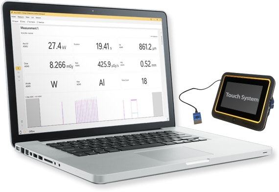
Accu-Gold 3
Simply Powerful
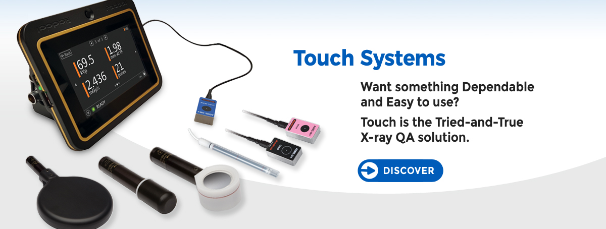
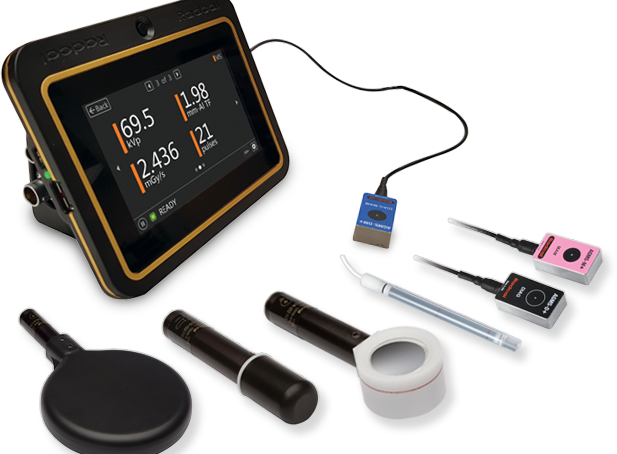
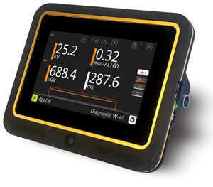
Touch Professional Systems
Want something Dependable
and Easy to use?
Touch is the Tried-and-True
X-ray QA solution.
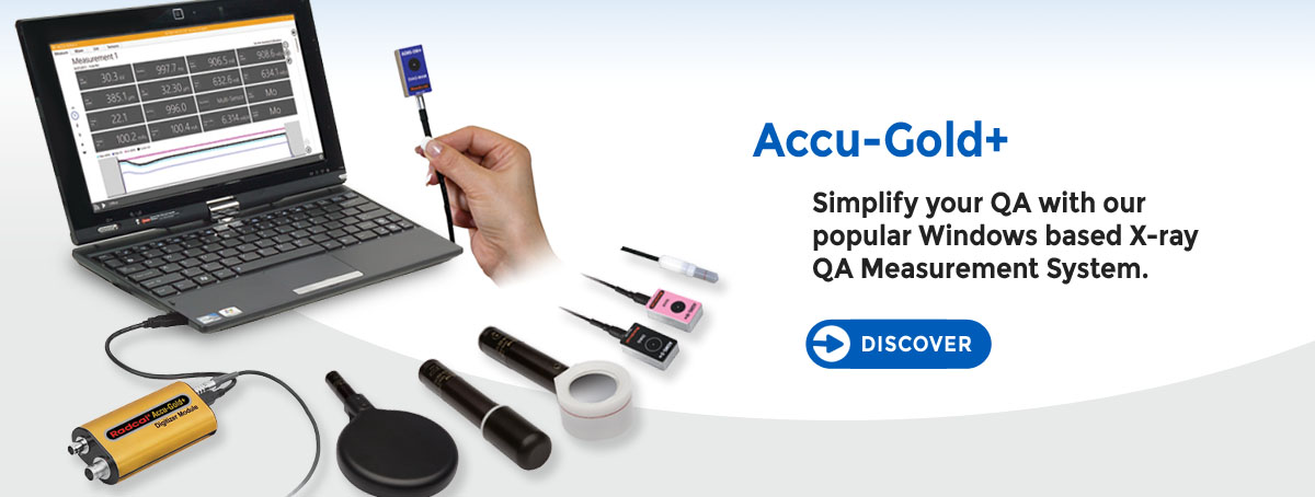
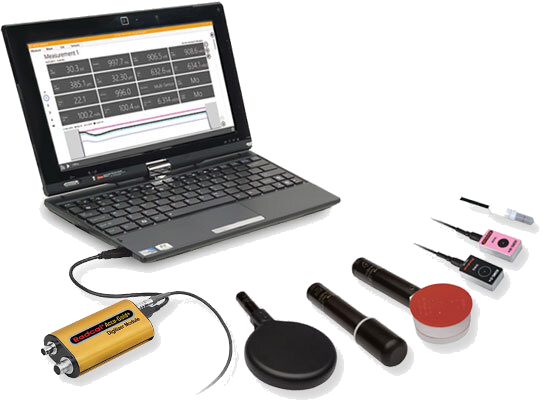
Accu-Gold+
Simplify your QA with our popular Windows based X-ray QA Measurement System
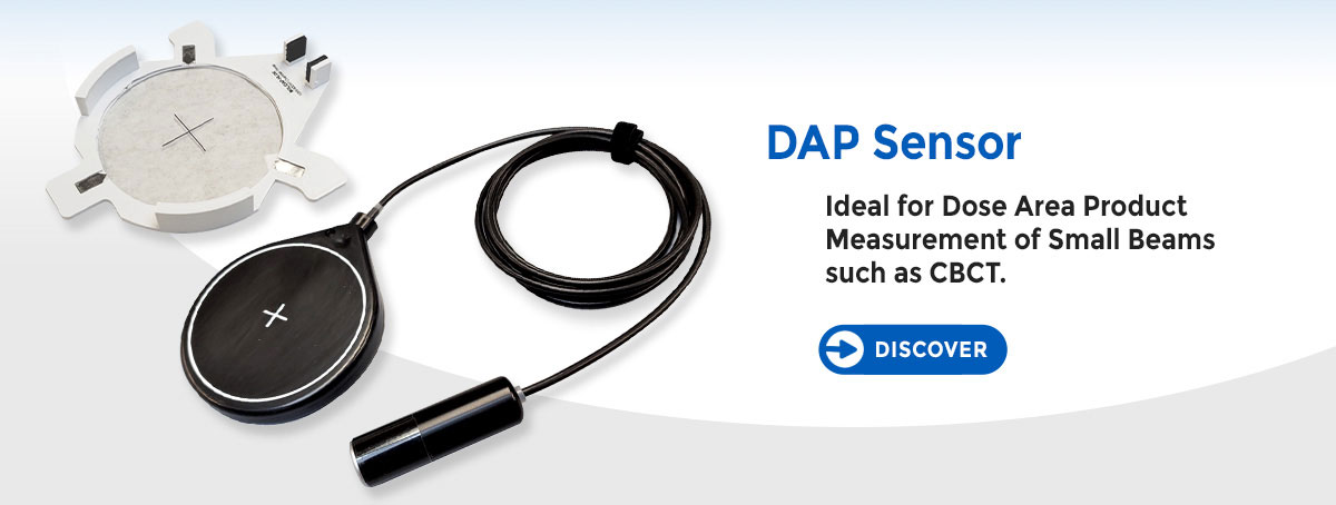
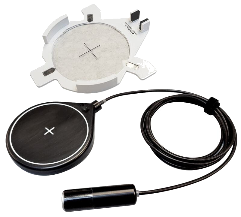
DAP Sensor
Ideal for Dose Area Product
Measurement of Small Beams
such as CBCT.

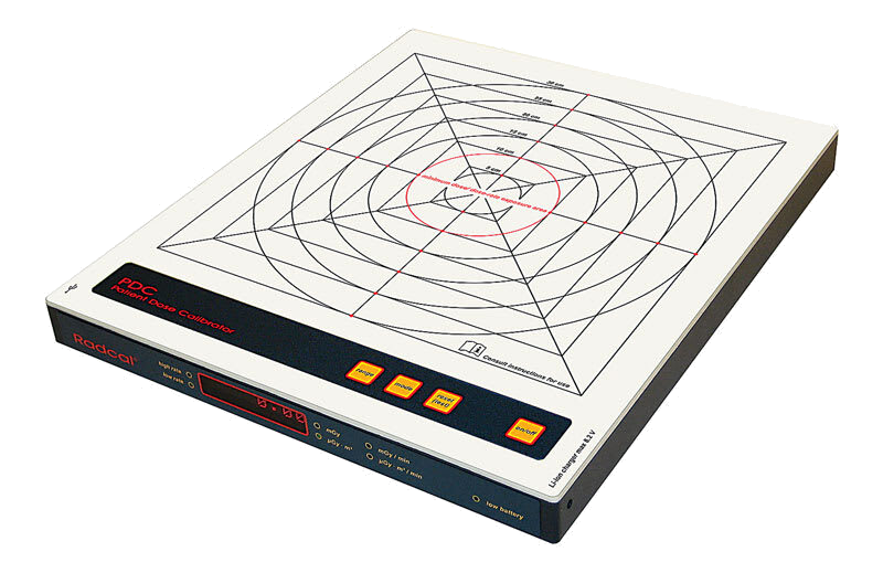
PDC-Patient Dose Calibrator
Save Time - Check the
Performance of Installed
DAP Meters in One Exposure!
News
Exciting News: IBA Successfully Acquires Radcal
Today we are excited to announce the acquisition of Radcal by IBA. We look forward to a positive future that strengthens both companies market positions and expands resources for all.
Service
![]() No Return Authorization number is required. For efficiency, please complete the Calibration/Repair Service Form and we will contact you with a price quote.
No Return Authorization number is required. For efficiency, please complete the Calibration/Repair Service Form and we will contact you with a price quote.
Providing Better Solutions for You